
Capacitors
200B Series BX Ceramic MLCs

ATC 200B Series Multilayer Capacitors
ATC, the industry leader, offers new improved ESR/ESL performance for the 200B Series BX Ceramic Multilayer Capacitors. This Series exhibits high volumetric efficiency with superior IR characteristics. Ceramic construction provides a rugged, hermetic package.
- Case B Size (.110" x .110")
- Capacitance Range 5000 pF to 0.1 µF
- Low ESR/ESL
- Mid-K
- Rugged Construction
- High Reliability
- Available with Encapsulation Option*
*For leaded styles only
Functional Applications
- Bypass
- Coupling
- DC Blocking
Circuit Applications
- Switching Power Supplies
- Broadband Coupling
- Medium Signal Amplifiers
| Electrical Specifications | |||
|---|---|---|---|
| Case Size: | B (.110" x .110") | Temperature Coefficient of Capacitance (TCC): | ±15% maximum (-55°C to +125°C) |
| Capacitance: | 5000 pF to 0.1 µF | Insulation Resistance: | 5000 pF to 0.1 MFd: 104 Megohms min. @ +25°C at rated WVDC 103 Megohms min. @ +125°C at rated WVDC |
| Tolerances: | See Capacitance Values | Dielectric Withstanding Voltage (DWV): | 250% of rated WVDC for 5 seconds. (125 VDC) |
| Working Voltage (WVDC): |
50 WVDC | Aging: | 3% maximum per decade hour |
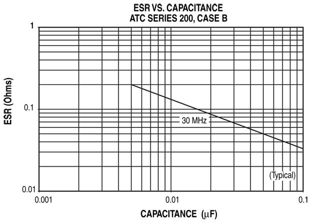
| ESR: | See RF Performance Data | Piezo Effects | Negligible |
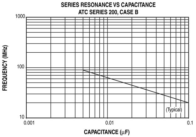
| FSR: | See RF Performance Data | ||
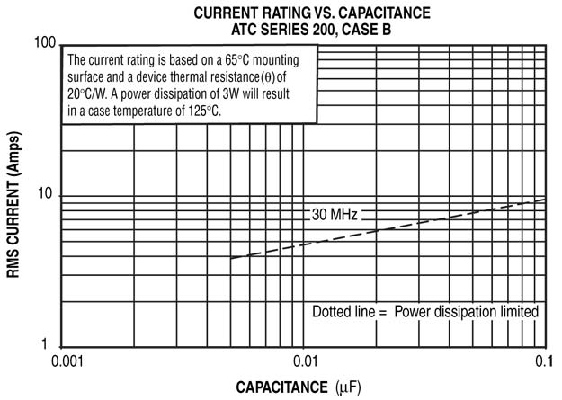
| RF Current: | See RF Performance Data | ||
| Mechanical Specifications | |||
|---|---|---|---|
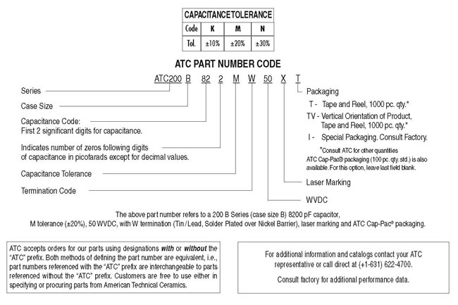
| Terminations: | T = Tin Plated over Nickel Barrier Termination* TN = Tin Plated over Non-Magnetic Barrier Termination* W = Tin/Lead, Solder Plated over Nickel Barrier Termination WN = Tin/Lead, Solder Plated over Non-Magnetic Barrier Termination P = Heavy Tin/Lead Coated, over Nickel Barrier Termination PN = Heavy Tin/Lead Coated, over Non-Magnetic Barrier Termination CA = Gold Plated over Nickel Barrier Termination* Leaded Styles: See note below. |
Terminal Strength: | Terminations for chips and pellets withstand a pull of 5 lbs. min., 15 lbs. typical, for 5 seconds in direction perpendicular to the termination surface of the capacitor. Test per MIL-STD-202, method 211. |
NOTE: Leaded styles are available: Microstrip (MS), Axial Ribbon (AR), Radial Ribbon (RR), Radial Wire (RW), Axial Wire (AW), Narrow Microstrip (NM), Narrow Axial Ribbon (NA) and Vertical Narrow Microstrip (H), Non-Mag Microstrip (MN), Non-Mag Axial Ribbon (AN), Non-Mag Radial Ribbon (FN), Non-Mag Radial Wire (RN), Non-Mag Axial Wire (BN), Non-Mag Narrow Microstrip (DN), Non-Mag Narrow Axial Ribbon (GN) and Non-Mag Vertical Narrow Microstrip (HN). All leads are high purity silver attached with high temperature solder and are RoHS compliant.
* RoHS Compliant
| Environmental Specifications | |||
|---|---|---|---|
| Life Test: | MIL-STD-202, Method 108, for 2000 hours, at 125°C. 200% WVDC applied. |
Thermal Shock: | MIL-STD-202, Method 107, Condition A. |
| Moisture Resistance: | MIL-STD-202, Method 106. | ||
| Capacitance Values | |||||||
|---|---|---|---|---|---|---|---|
| Cap. Code |
Cap. (pF) |
Tol. | Rated WVDC | Cap. Code |
Cap. (pF) |
Tol. | Rated WVDC |
| 502 | 5000 | K, M, N | 50 | 273 | 27,000 | K, M, N | 50 |
| 562 | 5600 | 333 | 33,000 | ||||
| 682 | 6800 | 393 | 39,000 | ||||
| 822 | 8200 | 473 | 47,000 | ||||
| 103 | 10,000 | 503 | 50,000 | ||||
| 123 | 12,000 | 563 | 56,000 | ||||
| 153 | 15,000 | 683 | 68,000 | ||||
| 183 | 18,000 | 823 | 82,000 | ||||
| 203 | 20,000 | 104 | 100,000 | ||||
| 223 | 22,000 | ||||||
VRMS = 0.707 x WVDC
SPECIAL VALUES, TOLERANCES, HIGHER WVDC AND MATCHING AVAILABLE.
ENCAPSULATION OPTION AVAILABLE.
PLEASE CONSULT FACTORY