
Capacitors
ATC 800R Series NPO Ceramic Ultra-Low ESR Multilayer Capacitors

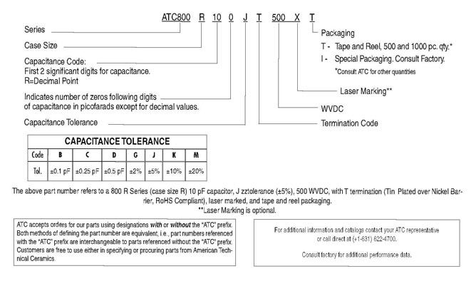
ATC 800R Series Multilayer Capacitors
ATC's 800R offers superb performance in demanding high RF applications requiring consistent and reliable operation. The combination of optimized case geometry, highly conductive electrode formulations and proprietary dielectrics yields the lowest ESR and superior heat transfer in high RF power applications. Ultra-low ESR and superior thermal performance ensure that the 800R Series products are your best choice for high RF power applications from UHF through microwave frequencies.
- Case R Size (.070" x .090")
- Capacitance Range 1 pF to 100 pF
- Rugged, reliable NPO dielectric
- Optimized for lowest ESR and superior heat transfer
- Optimized for highest self resonant frequency
- Capable of highest RF Power
- RoHS Compliant/Lead Free
Functional Applications
- UHF / HDTV Broadcast Transmitters
- Public safety Radio (APCO-25)
- Avionics
- Telecom
- WiMAX
- Microwave Communications Systems and Satellite Systems
- Medical Electronics
Circuit Applications
- High RF Power Filter Networks
- Combiners
- Couplers
- Matching Networks
- Output Coupling
- Antenna Coupling
- DC Blocking and Bypassing
| Electrical Specifications | |||
|---|---|---|---|
| Case Size: | R (.070” x .090”) | Temperature Coefficient of Capacitance (TCC): | 0 ±30 PPM/°C (-55°C to +125°C) |
| Capacitance: | 1 pF to 100 pF | Insulation Resistance: | 0.1 pF to 100 pF: 105 Megohms min. @ +25°C at rated WVDC 104 Megohms min. @ +125°C at rated WVDC |
| Tolerances: | See Capacitance Values | Dielectric Withstanding Voltage (DWV): | 250% of rated WVDC for 5 secs. |
| Working Voltage (WVDC): |
500 WVDC | Aging: | None |
| ESR: | See RF Performance Data | Piezo Effects | None |
| RF Current: | See RF Performance Data | ||
| Mechanical Specifications | |||
|---|---|---|---|
| Terminations: | T = Tin Plated over Nickel Barrier Termination* TN = Tin Plated over Non-Magnetic Barrier Termination* W = Tin/Lead, Solder Plated over Nickel Barrier Termination |
Terminal Strength: | Terminations for chips withstand a pull of 5 lbs. min., 15 lbs. typical, for 5 seconds in direction perpendicular to the termination surface of the capacitor. Test per MIL-STD-202, method 211. |
* RoHS Compliant
| Environmental Specifications | |||
|---|---|---|---|
| Life Test: | MIL-STD-202, Method 108, for 2000 hours, at 125°C. 200% WVDC applied. |
Thermal Shock: | MIL-STD-202, Method 107, Condition A. |
| Moisture Resistance: | MIL-STD-202, Method 106. | ||
| Capacitance Values | ||||||||||||||
|---|---|---|---|---|---|---|---|---|---|---|---|---|---|---|
| Cap. Code |
Cap. (pF) |
Tol. | Rated WVDC |
Cap. Code |
Cap. (pF) |
Tol. | Rated WVDC |
Cap. Code |
Cap. (pF) |
Tol. | Rated WVDC |
|||
| 1R0 | 1.0 | B, C, D |
500 | 3R9 | 3.9 | B, C, D | 500 |
220
|
22
|
G, J, K, M | 500 | |||
| 1R1 | 1.1 | 4R3 | 4.3 |
240
|
24
|
|||||||||
| 1R2 | 1.2 | 4R7 | 4.7 |
270
|
27
|
|||||||||
| 1R3 | 1.3 | 5R1 | 5.1 |
300
|
30
|
|||||||||
| 1R4 | 1.4 | 5R6 | 5.6 |
330
|
33
|
|||||||||
| 1R5 | 1.5 | 6R2 | 6.2 |
360
|
36
|
|||||||||
| 1R6 | 1.6 | 6R8 | 6.8 |
B, C, J,
K, M |
390
|
39
|
||||||||
| 1R7 | 1.7 | 7R5 | 7.5 |
430
|
43
|
|||||||||
| 1R8 | 1.8 | 8R2 | 8.2 |
470
|
47
|
|||||||||
| 1R9 | 1.9 | 9R1 | 9.1 |
510
|
51
|
|||||||||
| 2R0 | 2.0 | 100 | 10 |
G, J, K, M
|
560
|
56
|
||||||||
| 2R1 | 2.1 | 110 | 11 |
620
|
62
|
|||||||||
| 2R2 | 2.2 | 120 | 12 |
680
|
68
|
|||||||||
| 2R4 | 2.4 | 130 | 13 |
750
|
75
|
|||||||||
| 2R7 | 2.7 | 150 | 15 |
820
|
82
|
|||||||||
| 3R0 | 3.0 | 160 | 16 |
910
|
91
|
|||||||||
| 3R3 | 3.3 | 180 | 18 |
101
|
100
|
|||||||||
| 3R6 | 3.6 | 200 | 20 | |||||||||||
VRMS = 0.707 X WVDC
SPECIAL VALUES, TOLERANCES, HIGHER WVDC AND MATCHING AVAILABLE.
PLEASE CONSULT FACTORY.